Understanding Shielding Effectiveness Data: How to Interpret Test Results
Turning raw EMI/EMC data into actionable engineering insights.
Receiving a shielding effectiveness (SE) test report can be overwhelming. The data is often filled with logarithmic scales, complex frequency sweeps, and technical acronyms. However, correctly interpreting this data is the difference between a compliant facility and a costly security breach.
At Castle Compliance, we believe in transparency. We don’t just hand you a pass/fail certificate; we help you understand the physics behind the numbers. This guide breaks down how to read performance curves, understand the power of the decibel, and what to do if your system falls short.
1. The Power of the Decibel (dB)
Shielding effectiveness is not measured in linear percentages; it is measured in decibels (dB). The decibel is a logarithmic unit that expresses the ratio of the electromagnetic field intensity before it hits the shield versus the intensity after it passes through.
Because the scale is logarithmic, small jumps in dB represent massive leaps in protection. For example, moving from 20 dB to 40 dB doesn’t just double your protection—it increases the signal blocking capability by a factor of 10.
Shielding Attenuation Reference Table
Use this table to translate dB ratings into real-world blocking percentages:
| SE Level (dB) | Energy Blocked (%) | Energy Passing Through | Typical Application |
| 20 dB | 90% | 10% | Basic interference reduction (Consumer electronics) |
| 40 dB | 99% | 1% | Standard commercial grade (Server closets) |
| 60 dB | 99.9% | 0.1% | High-performance industrial / Medical Imaging |
| 80 dB | 99.99% | 0.01% | Precision R&D Labs / Military Grade |
| 100+ dB | 99.999%+ | < 0.001% | NSA 94-106 (SCIFs) & MIL-STD-188-125 (HEMP) |
Key Takeaway: For high-security environments (SCIFs or HEMP bunkers), even a 0.001% leak is considered a failure. This is why testing must be precise and rigorous.
2. The Critical Role of Dynamic Range
One of the most misunderstood aspects of SE testing is Dynamic Range. This metric defines the “measurement ceiling” or the maximum limit of the test setup. It is the difference between the strongest signal our equipment can transmit and the quietest noise floor our receiver can detect.
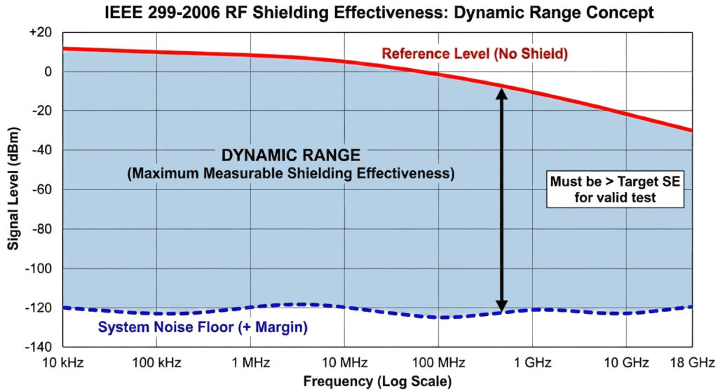
Why Dynamic Range Matters
Imagine you have a shield capable of blocking 100 dB, but the test equipment only has a dynamic range of 60 dB.
- The test results will flatline at 60 dB.
- You will not know if the shield is performing at 60 dB, 80 dB, or 100 dB because the equipment simply cannot “see” anything beyond its own noise floor.
Our Verification Process
To ensure accuracy, Castle Compliance performs a calibration phase before every test. We measure the source signal without any shielding to establish the baseline and compare it to the system’s noise floor. For high-stakes projects like NSA 94-106, we verify that our instrumentation has a sufficiently wide dynamic range to validate strict attenuation requirements.
3. Reading the Performance Curve (Frequency Sweep)
A single number (e.g., “60 dB average”) rarely tells the whole story. Most standard reports, such as those for ASTM D4935 or IEEE 299, present data as a Frequency Sweep. This graph plots shielding effectiveness (Y-axis) against frequency (X-axis).
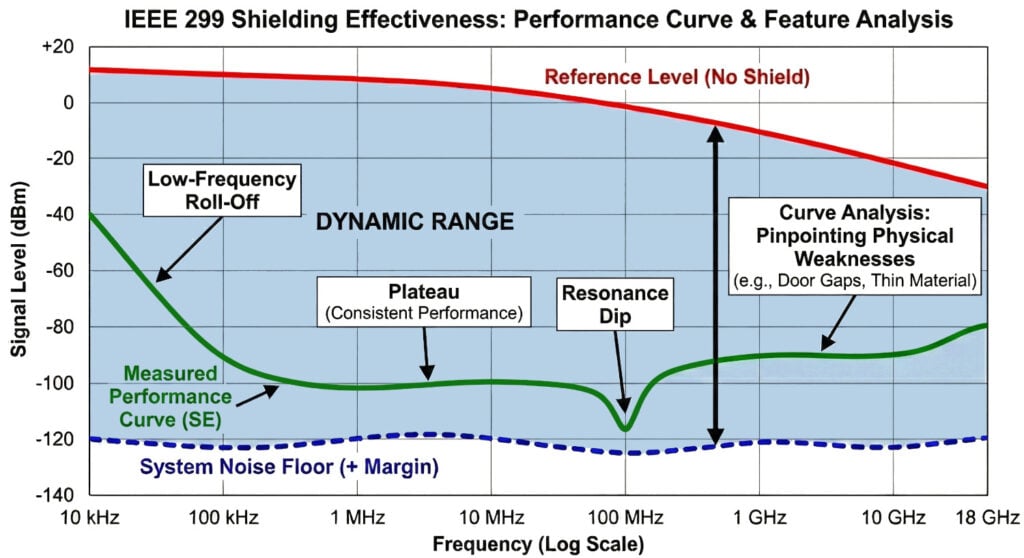
What to Look For on the Graph
- Plateaus: Flat, high sections of the curve indicate consistent performance where the material or enclosure is working effectively.
- Resonance Dips: You may see sharp “V-shaped” drops in the curve. These are Resonance Dips. They often indicate a physical dimension of the enclosure (or a seam length) that matches the wavelength of that specific frequency, allowing energy to pass through.
- Low-Frequency Roll-Off: At very low frequencies (kHz range), magnetic fields are harder to block than electric fields. It is common to see lower dB numbers at the start of the sweep, which rise as frequency increases.
We analyze these curves to pinpoint specific physical weaknesses, such as a door gap that only leaks at high frequencies or a material that is too thin for low-frequency magnetic shielding.
4. Interpreting Results by Standard
A “Pass” in one industry might be a “Fail” in another. We help you contextualize your data based on the specific standard you are targeting:
- ASTM D4935 (Materials): This test isolates the inherent potential of a material. If the data shows 80 dB here, but your final enclosure only tests at 40 dB, the issue is likely your construction methods (seams/joints), not the material itself.
- IEEE 299 & MIL-STD-285 (Enclosures): These tests validate the “weakest link.” The results will be dominated by leakage from doors, vents, and cable penetrations rather than the solid walls.
- NSA 94-106 (Secure Facilities): This is a binary pass/fail regime. The data is measured against strict NSA-mandated thresholds. A single frequency point dropping below the limit can prevent SCIF accreditation.
- MIL-STD-188-125 (HEMP): Interpretation here involves both attenuation data and Pulsed Current Injection (PCI) results. We verify that the enclosure not only blocks RF but that the filters successfully clamp high-voltage surges.
5. What Happens if a Test Fails?
A failing result is not a dead end; it is a roadmap for remediation. Because we capture real-time data across the spectrum, we can usually identify exactly why and where the failure occurred.
Our Troubleshooting Workflow
- Leak Detection: We use “sniffer” probes to locate the physical leak. Is it a door gasket? A loose fiber-optic feedthrough? A poorly bonded corner?
- Root Cause Analysis: We analyze the data to distinguish between material failure (e.g., inconsistent coating thickness) and assembly failure (e.g., gaps in conductive tape).
- Remediation: We provide specific, actionable engineering recommendations—such as upgrading waveguide vents, applying conductive epoxy, or tightening RF door latches—to bring the system into compliance.
6. Official Documentation & Reporting
The final deliverable of our service is a comprehensive test report designed to satisfy auditors, government officials, and internal stakeholders.
Your Report Will Include:
- System Calibration Data: Proof of dynamic range and reference levels.
- Raw Data Tables & Final SE Curves: Visual and numerical representations of performance.
- Pass/Fail Summary: A clear conclusion based on the specific requirements of your chosen standard (e.g., IEEE 299 or NSA 94-106).
- Images of Test Setup: Verification of antenna placement and sample preparation.
Need Help Analyzing Your Data?
Don’t leave your compliance status up to interpretation.
Contact Castle Compliance today for expert data analysis, troubleshooting, and consulting. Whether you need to decipher an existing report or commission a new test, our engineers ensure you have the full picture.